return to Learning Curriculum
LSET 4: Feed System Design
Original Author: Alexander Hodge '22, ahodge@mit.edu
Brief Intro
“The propellant feed system of a liquid rocket engine determines how the propellants are delivered from the tanks to the thrust chamber. These systems are generally classified as either pressure fed or pump fed. The pressure-fed system is simple and relies on the tank pressure to feed the propellants into the thrust chamber. This type of system is typically used for in-space propulsion applications and auxiliary propulsion applications requiring low system pressures and small quantities of propellants. In contrast, the pump-fed system is used for high pressure, high performance applications.” ->NASA Encyclopedia of Aerospace Engineering
This LSET will focus on the design requirements and performance characteristics of pressure-fed systems. Pump-fed systems may be discussed at a later time. I want to emphasize that the concepts in this LSET apply directly to more complicated feed systems, and are really crucial to overall engine design. In Industry, the feed system makes up a huge portion of the engine, and is in many ways even more crucial than the combustion chamber and nozzle design.
Please reach out to any of the members for questions/help on this! This is a lot of new and challenging info, so don’t stress yourself out by going at it completely alone.
By the end of this LSET, you should have a rough understanding of how to size and choose the components needed for a simple pressure-fed engine feed system. In other words, you should be able to (roughly) understand the design of the Helios P&ID (piping & instrumentation diagram) below, and what each component in the system does.
1. Pressure-fed Engine Scheme
Let’s start by looking at a simple pressure-fed system.
The image to the right is a diagram of a simple pressure-fed engine. We will ignore the heat exchanger, and assume the pressurized gas feeds directly into the fuel and oxidizer tanks.
|

2. Tanks
From the above diagram, 3 tanks will be necessary to effectively feed propellant to the engine, with 1 pressurant tank for both the fuel and oxidizer. For these problems, let’s assume that we have already been supplied with a proper pressurant tank, and only need to design the propellant tanks. Each propellant tank now needs to be properly sized & chosen to ensure that:
The engine will be supplied with propellant at the appropriate flow rate & pressure, for the desired duration of firing.
The tanks will withstand their respective predicted pressures without damage, for all tests and operations.
There’s a lot of constraints and conditions that go into the design of propellant tanks, but we're only going to cover the basics for now. We can justify this because our team is currently testing from a stationary stand, so many sizing and loading constraints that an actual rocket would impose are not relevant here.
Tank Volume Sizing
Read Huzel & Huang, Section 8.2, “Shape and Size of Propellant Tank” subsection for more info.
Lets address the first point from above. We can calculate a volume that will supply the engine with a desired flow rate for the firing duration by simply manipulating the equation for density.
rho =m/V => rho =(ṁ*t)/V => V=(ṁ*t)/rho
This is the required usable fuel volume, but not the required tank volume. In reality, tank’s are not filled completely full of propellant. If we have cryogenic propellants like liquid oxygen or liquid hydrogen, which have temperatures below -300F, it is crucial to leave extra space in the tank, as these propellants will boil off into gas when exposed to the hotter temperatures of the tank and piping. We call this extra space, from the top of the propellant’s liquid layer to the top of the tank, the tank ullage volume. The ullage volume will help prevent overpressurization as the propellant boils off.
An additional consideration when sizing our tanks is the trapped volume. After the engine is fired and the system is shut off, there may still be a residual volume in the bottom of the tank and in any pipes between the tank and shut-off valve, which we are not able to use. With this in mind, we define our required propellant tank volume:
Vtot=Vreq+Vu+Vt
where Vu= ullage volume, and Vt= trapped volume, Vreq= required propellant volume
For all proceeding questions, assume the following:
Fuel: Ethanol, diluted 70% | Oxidizer: Liquid Oxygen |
Density @25C :______ (kg/m3) FIND THIS HERE | Density:______ (kg/m3) FIND THIS HERE |
Mass flow rate: 5 kg/s | Mass flow rate: 7.5 kg/s |
Trapped volume: 0.1 m^3 | Trapped volume: 0.2 m^3 |
Engine firing duration: 200s | |
Tank ullage volume: 5% of propellant volume | |
Find the required usable oxidizer volume
- Find the design volume of the oxidizer tank
- Find the required usable fuel volume
- Find the design volume of the fuel tank
Tank Thickness Sizing
Read Huzel & Huang, 8.2, “Safety Factors” section, and 8.3, “Cylindrical Section” for more info
Now that we have the necessary tank volume, we need to make sure it can withstand any foreseeable pressures without damage. Let’s first introduce the safety factor. Safety factors apply some multiplicative value to our design constraint, ensuring that we are abiding by regulations. These regulations are often stated in official military or NASA documents, and they outline safety factors for different scenarios. When designing propellant tanks, the safety factor is applied to the yield stress (Fy) of the tank material at nominal temperature. The yield stress is how much force/area needs to be applied to the material for it to begin deforming in an irreversible way. So, with (yield stress)/(safety factor), we get the maximum allowable operating stress (Sw), which is the maximum stress we expect the tank to see at maximum tank pressure. This relation is described below for different scenarios:
Condition | Relation |
No hazard to personnel or vital equipment | Sw=Fy/1.25 |
Hazard to personnel or vital equipment | Sw=Fy/1.5 |
With our maximum operating stress, we can calculate the required wall thickness of our tanks using the following equation:
t = (pt*r)/(Sw*ew) | pt = maximum expected operating pressure (for tank) r = cylinder radius/dome radius Sw = maximum allowable operating stress ew = weld efficiency (assume this is 1) |
This is the minimum design thickness for a cylindrical tank, given our maximum stress and maximum operating pressure. In actuality, the thickness requirements differ for the cylindrical and dome sections of the tank, but this equation will still give us a fairly accurate value for the thickness requirement.
Let’s look at our fuel tank now. Due to sizing constraints on our test stand, and predetermined
engine design, assume the following:
Tank MEOP (maximum expected operating pressure) | 5 MPa |
Tank material | 316 Stainless Steel |
Material .2% yield stress | 290 MPa |
Material ultimate stress | 558 MPa |
Dome cap radius/Cylinder radius | 8 cm |
Weld efficiency | 1, (Purchased, one piece tank) |
Assume tank is a “hazard to personnel or vital equipment” | |
**To simplify things, let’s also assume that we have a perfectly cylindrical tank, and any stress at the capped ends can be ignored.
Using the relevant equations found in the reading, find the following:
i) Tank maximum allowing operating stress. Explain what this means
ii) Required tank wall thickness
iii) OPTIONAL: using the below equations, find the “burst factor”. What do you think this value represents?
BF = pburst/pt pburst = (Fu*t) / r
BF = burst factor, t = wall thickness, r = tank radius, Fu = material ultimate stress, pt = MEOP
3. Regulators
Regulators are used in a feed system to maintain a desired pressure level. In most design schemes, the regulator takes in the high pressure gas from the pressurant tank at its inlet, and regulates it down to the desired system pressure at its outlet, which continues towards the propellant tanks. In a perfect world, the regulator will continue to supply a constant output pressure during the duration of operation. In practice, the regulator outlet pressure will change, and that change depends on a few factors, described below: a. Flow coefficient(Cv), Cv=QSGP, Q=volumetric flow rateSG=fluid specific gravity,P=pressure drop across regulator
b. Changing inlet pressure
c. Changing flow rate
|
A. For our pressurant tank, assume a delivery pressure psys=2000 psig, flow rate Q=2000 galminand our pressurant is gaseous Nitrogen. If we want the regulator to continue functioning nominally down to a supply pressure of 2200psig, what is the required Cv? Is this a minimum or maximum constraint? Explain why.

B. Shown above is a graph pulled from a regulator’s company data sheet. Using this graph, the flow rate/delivery pressure from question A, and an inlet pressure of 4500 psig, determine if the regulator represented in this graph would satisfy our requirements. You will need to “guess” an additional curve that fits with the trends of the existing curves. (hint: 8.02 SCFH = 1 gal/min)
4. Shut-off Valves
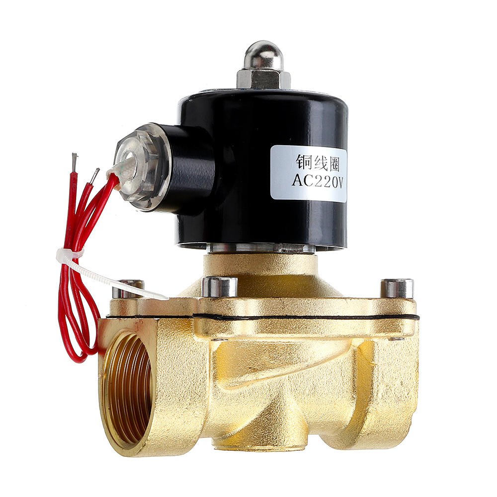
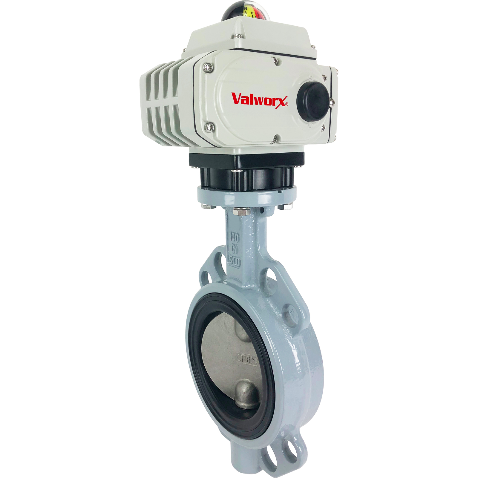
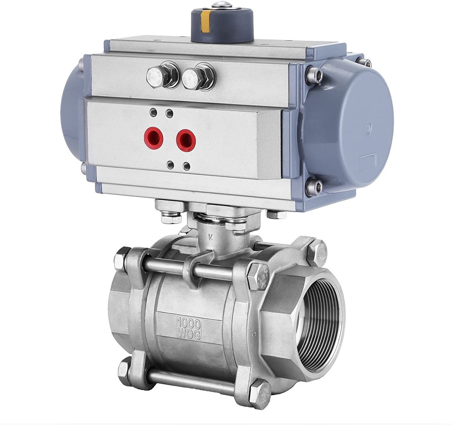
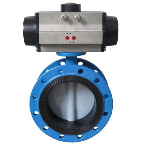
“Shut-off” valves really just refer to all valves in the system that serve as gates to the flow. We add valves to our system to have control on different steps of operation. This includes propellant tank pressurization, engine firing, system venting, propellant filling, and anything in between. The below table provides a brief overview of some types of shut-off valves that are often used in a simple pressure-fed engine feed system. Note: although I literally just found these pictures off google, choosing valves for your system is a CRUCIAL (and surprisingly fun) area of design for pressure-fed engines. In industry, things get even more interesting, as it is common to design custom valves in-house.
Ball Valve Very common valve. Large range of applications. | Solenoid Valve Uses a solenoid coil (8.02) to lift a piston from its seat, allowing flow | Butterfly Valve Simple, high flow capability. Design complexifies in high pressure applications. | |
Manual Obviously you need to actuate yourself. These can be used for propellant filling, safety, and redundancy. | (Not really a thing) | ||
Electrically Activated These valves have slower actuation, but higher actuation torque. Often used for pressurization & throttle valves. | |||
Pneumatically (and electrically) actuated These valves have much faster actuation, but also lower actuation torque. Often used for pressurization & throttle valves. |

One of the main things to consider when choosing valve components is the resulting pressure drop through the valve. This is important to consider, because if we have many valves in our system that cause large pressure drops, the resulting pressure at the engine inlet will be much lower than desired. A COTS (commercial off the shelf) valve will usually have an accompanying flow coefficient from its data sheet. If you know the basic characteristics of your feed system, you can use the flow coefficient equation (discussed earlier) to calculate the pressure drop across each valve, and ensure your valve pressure drops are not detrimental.
A. Now, let’s choose some valves for a very simple propellant feed system, but only the fuel side. For this exercise, we want you to choose what you think are the best valves (among the 3 below) to separate the pressurant tank, fuel tank, and engine. There isn’t necessarily one right answer, but use the information from the above table, the presentation slides, and your intuition to support a design. Now, say that we have the following valves & system constraints available in the table below. For each valve you choose to use, answer/explain the following:
**You’ll need to convert things to SI units**
i) explain the placement of the valve. What is its function here?
ii) why use this valve at this spot, and not one of the others?
iii) what will be the pressure drop across this valve when the system is operating?
System Constraints - Q=100,000 gal/min - fuel: pure ethanol @25C FIND THIS HERE | Valve 1  Cv = .02 | Valve 2 Cv = 0.15 | Valve 3
Cv = 0.008 |
5. Pressure Relief Components
Relief components are extremely important safety mechanisms used in feed systems. Their function is to release pressure from the system if it gets too high. Without pressure relief components, a scenario where the system becomes significantly overpressured could cause catastrophic damage.
Two very common pressure relief components are relief valves, and burst disks.
Burst Disk | Relief Valve |
Burst disks are, as you’d expect, disks that burst when the pressure reaches a certain set value. Some burst disk components have replaceable disks, while others are single use. Vendors offer burst disk models that are designed for a wide range of set pressures. |
The most common type of relief valve design is like the one shown above. The gasket or plug, compressed by a spring, is lifted to allow flow when the pressure is high enough. Relief valves are largely reusable, and can also be designing for a wide range of set pressures |

Two important factors to consider when choosing pressure relief components is their set pressure, and flow capability. Set pressure is quite obvious, as you would choose the value to be some safety factor above your feed system’s expected operating pressure.
The ‘flow capability’, as we are calling it, takes a bit more thinking to figure out. Consider a scenario where the feed system is pressurized but not operating. Suddenly, the regulator on the pressurant tank fails, causing additional fluid to flow into the feed system, thus increasing the system pressure. In this situation, the relief valve activates, but we want to ensure that the fluid exits through the relief valve at a higher rate than it is entering from the tank, otherwise the system pressure will continue to rise. Luckily, we can determine if our relief valve is capable of this flow using something called the discharge coefficient, which is found using the equation below.
C d = mdot/(A*sqrt(2*rho*dP)) , mdot = mass flow rate, rho = fluid density, P = valve pressure drop, A = orifice area*
*orifice area is the smallest orifice in the valve
The discharge coefficient is a ratio of the theoretical and actual flow rate across an orifice (valve). You can often find the discharge coefficient from the component’s data sheet. You will eventually learn about discharge coefficients if you take enough fluids classes, but one thing to note is you can even find an unknown discharge coefficient if you have the flow coefficient, and vice versa. Read this short page for more in-depth info on Cd.
A. Using the following info, determine if the supposed relief valve can be used in our system.
**You’ll need to convert things to SI units**
mdot_failure=1.5 kg/s | p_sys=800psi | fluid = pure ethanol @25C FIND THIS HERE | Cd = .25 | A_orifice= 6.95e-5 m2 |
6. Check Valves
In pressurized fluid systems, it is possible to have something called “back-flow”, in which the flow, as you would imagine, travels in the opposite direction that you desire. In a pressure-fed system, one scenario could be the cryogenic oxidizer traveling backwards out of the propellant tank, and into the pressurant gas lines. This could be detrimental, as the pressurant side components are likely not rated to cryo temperatures, and would be susceptible to damage. To prevent any backflow scenarios, we strategically place check valves in the feed system, creating one-way gates along the flow.
Check valves, to reiterate, are very important components used in pressure-fed feed systems. A check valve is a valve that only allows flow in one direction. There’s actually many different types of check valves, all with different applications. |

Check valves are subject to the same pressure drop and flow requirements as the shut-off valves in the system. Flow coefficients for check valves can be found in supplier data sheets, and pressure drop calculations are done in the same way as discussed earlier.
7. Overall Design
Understanding the proper placement of these components is the next step in learning feed system design. There is an aspect of intuition and experience with this, and these are developed from a full understanding of each component’s use.
Lets first go over the layout of the Helios feed system. Refer to the key below for all diagrams.

a. First, we separate our pressurant tank, propellant tank, and engine with the necessary valves. The manual valve opens the pressurant, and it is regulated down to system pressure on both sides.
b. Actuating ball valves are on either side of the propellant tanks. Check valves are on either side as well to prevent back flow to the pressurant tank and propellant tanks respectively.

c. Now let’s incorporate the relief valves and fill valves. The LOX side has a relief valve and burst disk for extra precaution.
d. The fill valves allow us to pour the Ethanol and LOX into the propellant tanks (when unpressurized).

e. Next, we incorporate all of our solenoid valves. Our main control valves are pneumatically actuated ball valves, and have solenoid valves attached that are pressurized with low psi air.
f. We also added solenoid vent valves next to the relief components, which we can actuate from distance to depressurize the system after operation, or in a failure event. It’s not shown in this diagram, but we actually have 2 solenoid vent valves on each side for redundancy.

g. At this point, the feed system is complete, and we just need to add all of the pressure sensors. Pressure gauges are used to view the live pressure transients over video, and the pressure transducers are used to log the pressure profile.

Referencing the P&ID diagram above, label the valve components on the images shown. Specifically, label all of the control valves, relief valves, regulators, tanks, etc. I’d recommend copying the image to powerpoint for easier editing, or you can just explain it verbally.
Closing
There’s still a lot more to talk about for pressure-fed feed system design, and we’ll go over that soon! And this is still just the tip of the iceberg for feed systems in general. If you want to learn about more complex feed systems, look up Gas Generator and Staged Combustion engine cycles. These are the systems used commonly for large industry-level engines, and they introduce another awesome topic: ~turbomachinery~
return to Learning Curriculum