Part | Component Status | Responsible Engineers |
|---|---|---|
| Aeroshells | Manufacturing Prep | Emma Suh 2023 emmasuh@mit.edu |
What is an aeroshell?
An aeroshell is a rigid heat-shielded shell that protects a spacecraft component from pressure, heat, and possible debris created by drag during atmospheric entry.
What does Rocket Team use aeroshells for?
Because there is not enough room inside the rocket for cameras and we need both upwards and downwards facing cameras (as opposed to outwards facing), we must place them outside the rocket’s airframe. And since you can’t just glue the cameras on the rocket and call it a day, we must make aeroshells to reduce drag and protect them.
Phoenix’s cameras are different from demo’s (bigger and needed to be housed with their PCBs), so the aeroshells needed a redesign.
Full Camera Designs:
PCB Aeroshell


Concept Description:
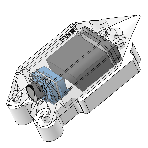
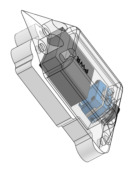
An aeroshell that houses both the camera and its PCB outside of the airframe. The shell (transparent) and holder (opaque) sandwich the airframe of the rocket with 4 screws. Holes in the airframe are made for screws, camera body, and PCB. The camera nests inside the holder and is held down by the shell. The PCB is screwed into the base of the holder. The bottom lens of the camera must be removed.
Pros:
| Cons:
|
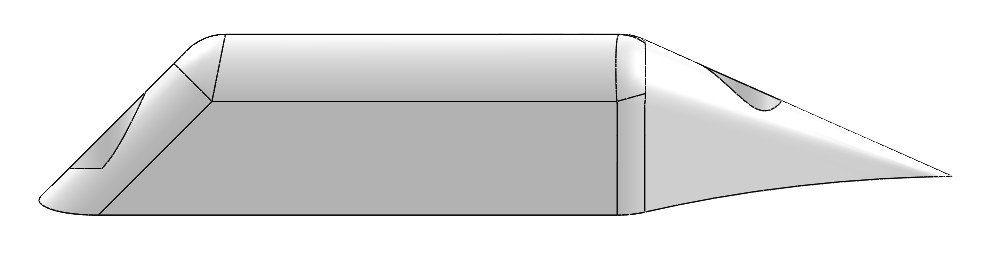
Mirrored Aeroshell
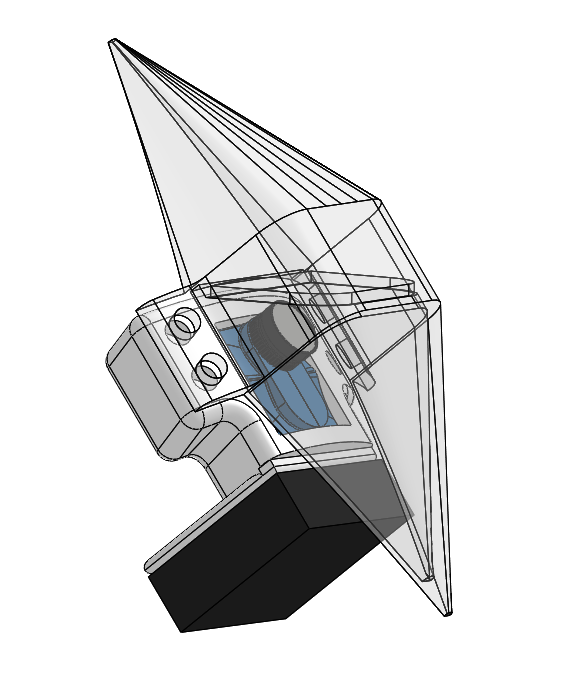
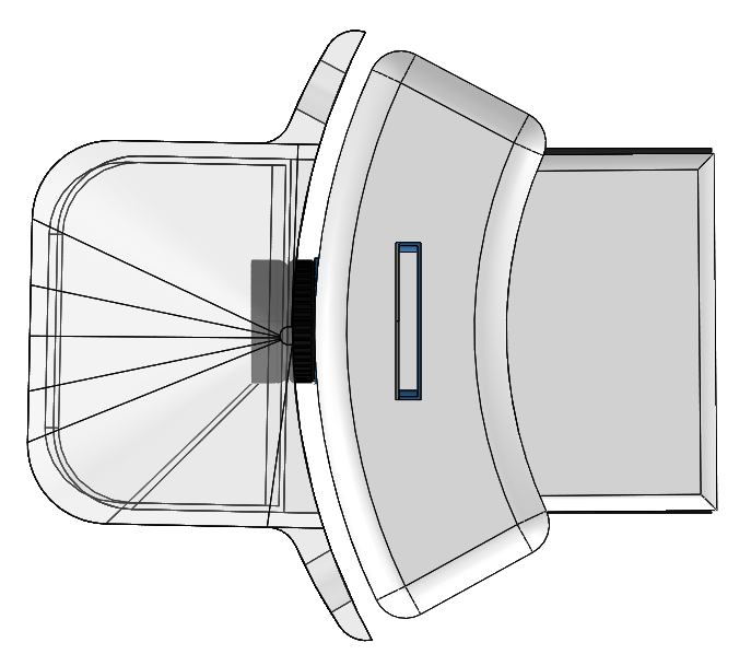
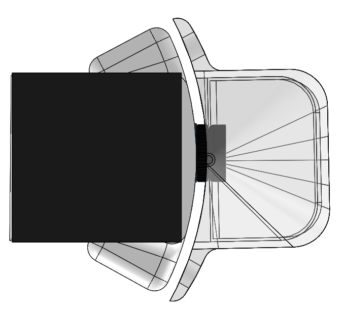

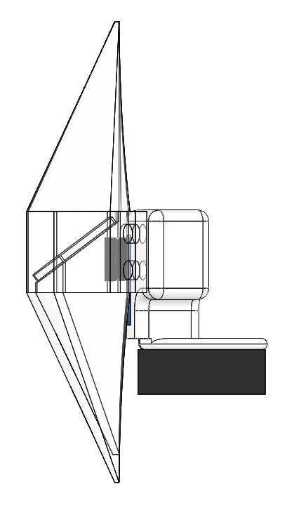
Concept Description:
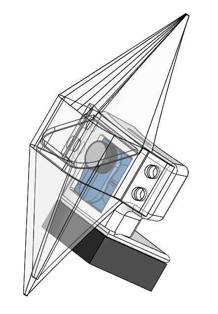
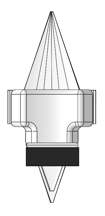
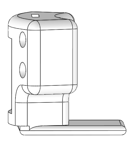
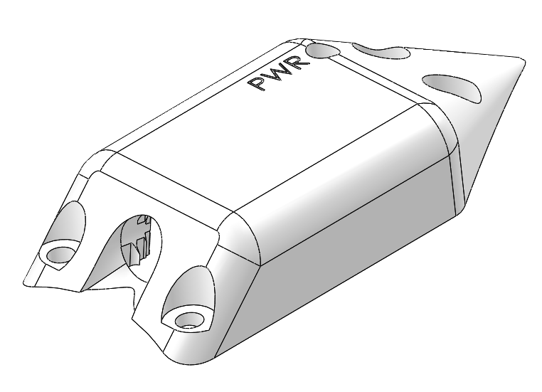
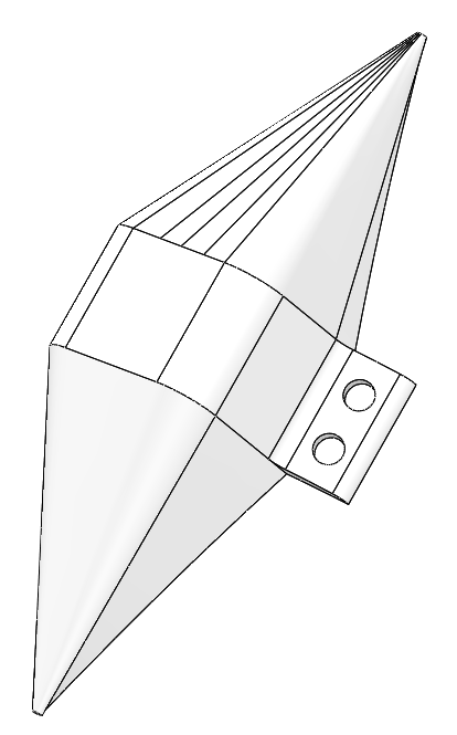
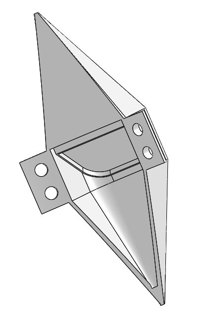
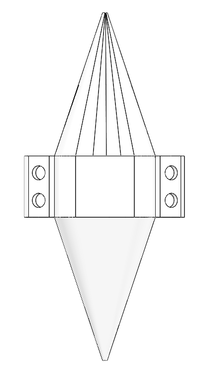
An aeroshell that holds both the camera and PCB inside the airframe. The camera lens however, is poking out. The shell (transparent) and holder (opaque) sandwich the airframe of the rocket with 4 screws. Holes in the airframe are made for screws and the camera lens. The camera is held steady by the holder, which has a slit for the ribbon cable to connect it to its PCB. The holder has a jutting plate that the PCB can be mounted and screwed onto. The bottom lens of the camera must be removed so as not to block the camera’s angled view.
The shell has a slanted wall on which a mirror will be mounted. It is set at a 53 degree angle (which will provide a 8 degree angle camera view from the airframe). Ideally, part of the aeroshell will be made of clear material.
Pros:
| Cons:
|
Dimension Comparison | ||
PCB Aeroshell | Mirrored Aeroshell | |
Length (down airframe) | 3.4 in | 4.13 in |
Width (across airframe) | 1.5 in | 1.66 in |
Height (radially away from airframe) | 0.67 in | 0.91 in |
Mass (estimate with camera and PCB) | 0.10 lbs | 0.11 lbs |
Volume (estimate with camera and PCB) | 2.8 in^3 | 3 in^3 |
Surface area (estimate with camera and PCB) | 43.84 in^2 | 49.37 in^2 |
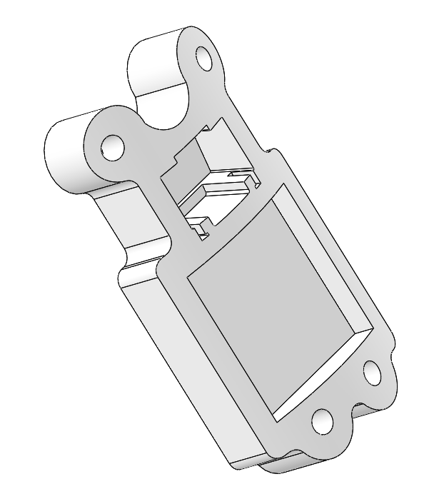
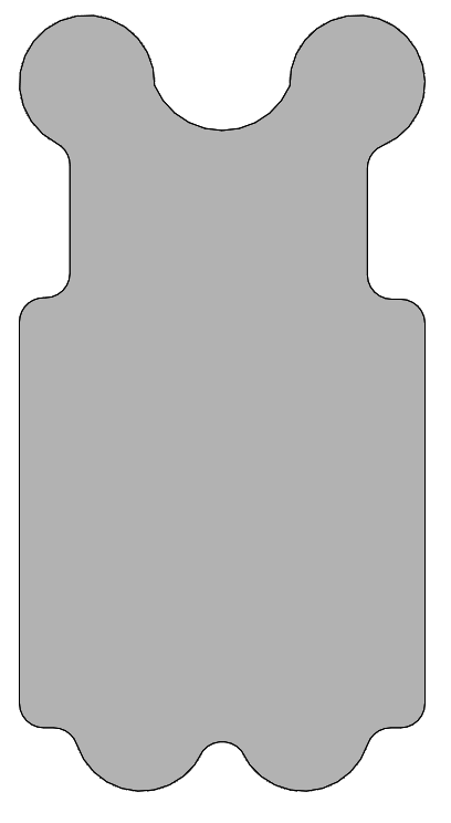
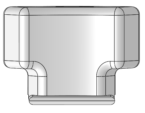
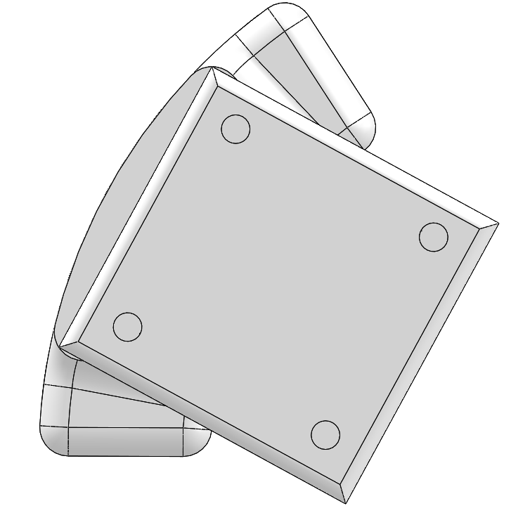
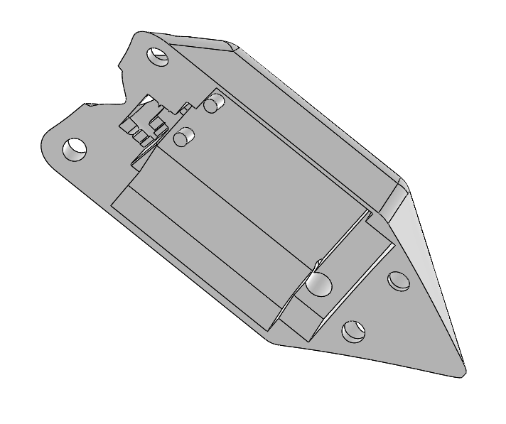
Holder:
Purpose: Hold the bottom of the components in place as a supportive base, often connects the airframe and the shell
Features:
Can either be designed to sandwich the airframe (as you’ve seen in these examples), or in some designs, the holder is on the outside between the shell and the airframe
The carved out base for the camera should usually be at an angle (angle depends on the camera and design and usually ranges from 5-15 degrees) so as to maximize the camera’s field of view (FOV)
Screw holes are usually threaded.
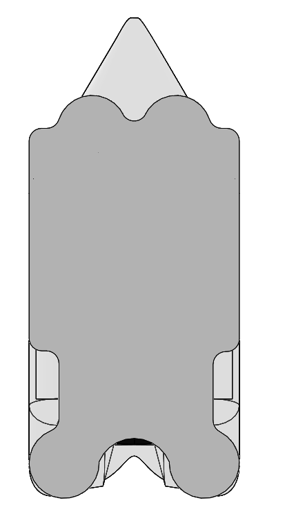
PCB Aeroshell Example:
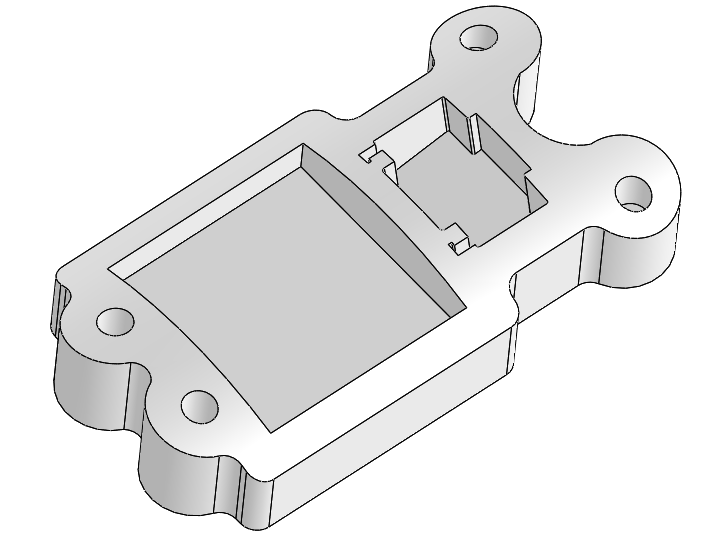
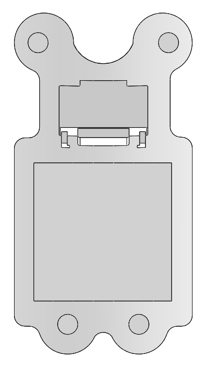
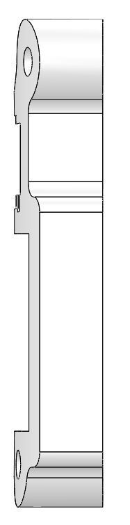
Mirrored Aeroshell Example:
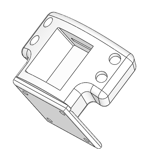

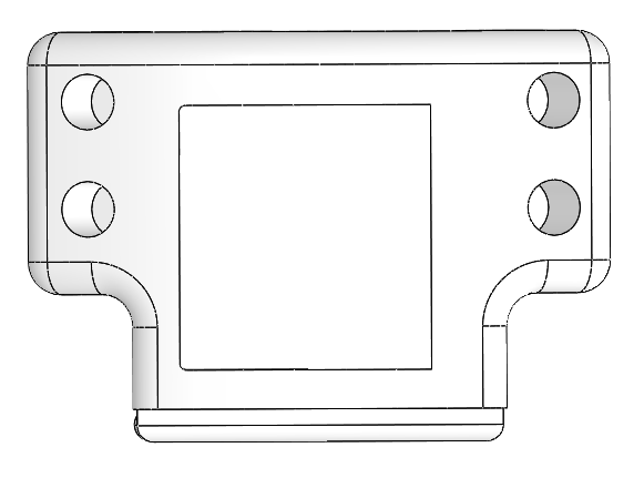
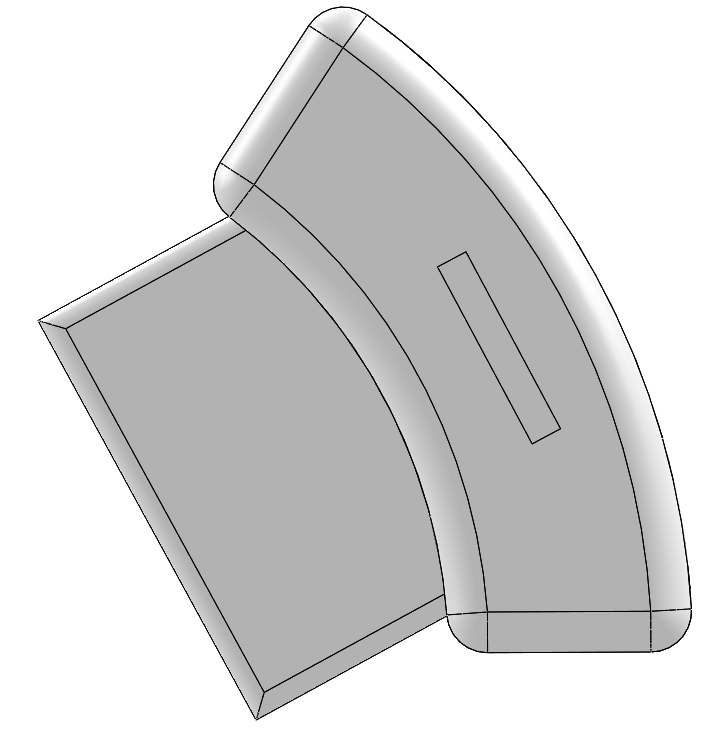
Shell:
Purpose: Hold the components down, maximize the camera’s FOV, maintain an aerodynamic shape
Features:
Sometimes the shells will have stoppers coming down from their roof. This is to prevent the components from shaking and offer more stability.
It’s the component between the atmosphere and the lens, so make sure it covers as much of the camera as possible.
Screw holes on here are not usually threaded. Just make sure that there is a lip for the screw head.
If a hole for the lens is necessary, make sure it’s at the proper angle.
It’s a plus if the shell is designed so that the aeroshell can be used for upwards or downwards video.
PCB Aeroshell Example:
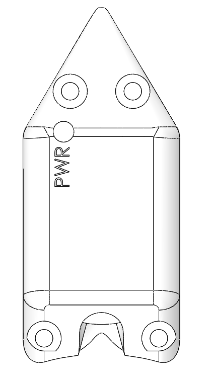

Mirrored Aeroshell Example:


Side tips for making aeroshells:
AIRFRAME INTERFACE: Make sure to consider the circumference of the airframe. If the part is outside the airframe, the circumference of it’s part interfacing with the airframe should be slightly (~0.001 in) greater and if on the inside, slightly less
MATERIALS: Consider the materials that your design will require and how easy it is to work with those materials. In the case of the mirrored aeroshell, we needed a clear material that could take the design’s shape, but the two ideas that came to mind (bending polycarb, using transparent filament) were not feasible. Another way around this would be to design around the materials you would like to use (for example, if you are thinking of cutting polycarb panels, those parts should not be curved)
ASSEMBLY: Consider how the aeroshell parts will be assembled with the camera, PCB, and rocket. Try to minimize the amount of steps, make it as intuitive as possible so it can be done by other teammates, and keep in mind the order of assembly relative to other rocket components.
CAD: When CAD-ing the aeroshell, try to make dimensions adjustable so that it can be easily changed if the fit is not perfect the first time (which it most likely won’t be!)
EDGES: Filleted edges = good and pretty
SPACE: Cut away chunks of the aeroshell that are unnecessarily taking up space. Reduce weight! Also you can cut them up prettily to make the design cooler.
To whoever is making next year’s design or if you just have questions about the aeroshells I made, feel free to contact me @emmasuh@mit.edu.