Requirements
- The launch vehicle shall carry no less than 8.8 lbs. of payload.
- The payload(s) submitted for weigh-in shall not be inextricably connected to other launch vehicle associated components while being weighed
- Payloads shall not contain significant quantities of lead or other heavy metals. Additionally, payload shall not contain any hazardous materials that impact the health and safety of team members, staff, the general public, the convention center, or the launch site itself.
- Any functional scientific experiment or technology demonstration payload and its associated structure may be constructed in any form factor
- Teams whose functional payloads do adopt the Payload Cube Unit physical standard will be awarded bonus points in the IREC. To meet this requirement, a payload will have to fit completely in a Payload Cube Unit dispenser with nothing protruding or physically connecting outside
- The payload design may incorporate up to 2.25 lbs. of non-functional “boiler-plate” mass to meet the required mass minimum. This non-functional “boiler-plate mass must be weighed separately from the rest of the payload to ensure it does not exceed the allowed mass as specified above.
All requirements: https://www.soundingrocket.org/uploads/9/0/6/4/9064598/sa_cup_irec_rules_and_requirements_document_-2024_v1.4_20240304.pdf
Judging Criteria
- Scientific or Technical Objective(s) (400 points)
- How relevant and well-designed is your scientific or technical objective?
- Payload Construction and Overall Professionalism (200 points)
- Includes make/buy decisions, craftsmanship, material usage, poster, handouts, reports, etc.
- Readiness / Turnkey Operation (100 points)
- Will the payload interfere with launch operations? Will the payload operate after hours of launch preparation, rail time, heat, waiting for other launches, etc?
- Execution of Objective(s) (300 points)
- How well did it accomplish the objective(s)? Note that no report equals zero points and rocket failure results in 150 points (half credit – don’t know if payload would have worked or not)
SDL Payload Challenge Website: https://www.soundingrocket.org/sdl-payload-challenge.html
Research
10/6/24
Ideas:
Kareena:
- We can take an EAPS route
Yeast production:
- Will ask my advisor for more deets
- Can show the impacts of radiation
Airborne particles/sample the atmosphere (idea from the summer)
- Problem: More experimental/scientific, understand airborne particles/microorganisms at high altitudes
- Projects: measure and study airborne particles during ascent/descent to understand what/how many exist at different points of trajectory (sensor?)
- More of a climate approach, we could tie it into pollution or something along those lines
- https://www.apogeerockets.com/Peak-of-Flight/Newsletter526
Quadcopter deployment
- Have the rocket house a small uav and have it deploy at some point during the rocket’s flight
Santiago:
How does height affect background radiation and UV?
- Ozone concentration vs. height, possibly combine with above to see how ozone concentration can affect UV
- Effects on materials?
Food storage
- Particularly, wet and solid foods. Are they significantly affected in quality/shape/texture/etc.
Measuring relativistic effects on time via rocket acceleration
Test the usage and efficiency of IV drips and pumps
- Medical uses
Tiffany:
- Astronauts experience losses in bone density during their time in space as a result of microgravity. Does anything happen during takeoff?
- How increased g forces impacts crystal growth
Sydney’s Group:

09/22/24:
Cold Brew:
- Normally brewed overnight
- Regular cold brew is normally steeped for 10-12 hours
- Can be brewed faster under higher pressure
- Use a french press/aeropress method to compress the grounds
- Pressure of compression will be tested
- Will be brewed during launch and using room temperature water
- Will have a control group that will be brewed using regular cold brew methods on the ground
- Grounds
- Coarse
- Will be bought pre-grounded (from whatever company sponsors us)
09/15/24:
Prelim Payload Goals/Purpose:
Purpose:
Using the acceleration of the rocket to simulate a high gravity environment to complete an experiment in a unique setting that is hard to achieve under other circumstances
Yeast
- Paper: Microbial growth at hyperaccelerations up to 403,627 × g
- Baker’s yeast: Saccharomyces cerevisiae
- Super high acceleration (lowest in this study was 100 g)
- Less growth under high acceleration
- Some kind of sedimentation effect and concentration gradient in the cells
- Time scale of hours
- Paper: Effects of Low-Shear Modeled Microgravity on Cell Function, Gene Expression, and Phenotype in Saccharomyces cerevisiae
- We have more microgravity than high gravity, microgravity effects might be easier to measure
- Time scale of hours
Yeast is affected by changes in acceleration, but it seems that the time scale required is not realistic for our purposes (rocket launch to touchdown is on the order of 1 minute, the above papers study 10s and 100s of minutes)
Coffee
Materials of Experiment:
- Vessel
- Grounds
- Water
- Testing Equipment
Design Concerns and Considerations:
- Containment:
- Keep grounds + water in container
- Coffee says isolated
- Rocket Orientation/Descent
- Descent rate
- Orientation (upside down, sideways)
- Impact
- Can we continue to contain the experiment-
- Evaluation of Success:
- Semi-immediate results/data
- Heating/Water temp-
Possible Development of a cold brew design?
10/10/24
Spine:
- Materials:
- Model section of spine (focus on vertebrae or discs?)
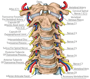
- Upper spine (neck area) - feels the most force because head is heavy - part of the spine that becomes weakest in older adults
- Lower spine - for someone with a medical condition
- Brace (non-invasive)
- Extra: skin like material to see how much damage the brace would do
- Challenges:
- How will the brace enact force on the test spine
- Finding a good fake bone material
- Spine has bone and ligament sections. Do we also need to model the squishy ligament sections for this to be accurate? I feel like the squishy ligament sections would respond most to compression (more squishy than bone) so maybe idk
- How to brace non-invasively inside the payload?
- What are we measuring? How will we collected data? - displacement, something to measure forces between vertebrae?
- Do we need to simulate weight of the head? - scale down the spine and just add weights on top
- Plan:
- At least one braced ‘spine’ and one control
- Do we want multiple brace designs
- Create brace similar to traditional medical brace
- Angled spine to be more realistic to how astronauts actually sit in rocket
IV Drip/Insulin Pump:
- Individuals in air travel have often been reported to experience hypoglycemia (too much insulin is delivered by the pump during takeoff?)
- Materials
- Insulin/IV drip
- Force comes from gravitational pull, so the drip bag must be kept higher than the place insulin/IV fluid is delivered
- Mechanical IV/ insulin pump
- Functions like a syringe
- Doesn’t function based on gravity, will it still be impacted by the increased g forces?
- Delivery site
- Synthetic model of human fatty tissue?
- Challenges
- What are we measuring?
- Flow rate through a small tube? Fluid delivered somewhere?
- Goal to maintain a constant flow rate (drip rate) throughout flight?
10/13/2024
asdf
We did a intense brainstorm and design session for the updated payload project. We decided on the neck brace, and conducted research on different elements of the project.
Project Aurora- Payload Design
Purpose/Proposal: Sydney
Current NASA astronaut physical requirements:
Distant and near visual acuity must be correctable to 20/20 in each eye, blood pressure not to exceed 140/90 measured in a sitting position, and the candidate must have a standing height between 62 and 75 inches.
NASA Astronaut training:
The Astronaut Candidates undergo a training and evaluation period lasting approximately 2 years. As part of the Astronaut Candidate training program, candidates are required to complete military water survival before beginning their flying syllabus, and become SCUBA qualified to prepare them for spacewalk training. Consequently, all Astronaut Candidates are required to pass a swimming test during their first month of training. They must swim 3 lengths of a 25- meter pool without stopping, and then swim 3 lengths of the pool in a flight suit and tennis shoes with no time limit. They must also tread water continuously for 10 minutes wearing a flight suit. Candidates are also exposed to the problems associated with high (hyperbaric) and low (hypobaric) atmospheric pressures in the altitude chambers and learn to deal with emergencies associated with these conditions. In addition, Astronaut Candidates are given exposure to the microgravity of space flight during flights in a modified jet aircraft as it performs parabolic maneuvers that produce periods of weightlessness for about 20 seconds. The aircraft then returns to the original altitude and the sequence is repeated up to 40 times in a day.
Civilian spacefight requirements:
- Be within the following height and weight range: 5’0” 110 lbs. and 6’4” 223 lbs.
- Dress themselves in a one-piece, zip-up flight suit;
- Climb the New Shepard Launch Tower (equivalent to 7 flights of stairs) in under ninety (90) seconds; Walk quickly across uneven surfaces, such as a ramp or a deck with occasional steps.
Blue Origin will not evaluate the Astronaut’s medical fitness to participate in the Flight. If the Astronaut has questions about medical conditions and/or their ability to fly on New Shepard, the Astronaut must contact their medical professional and reach that determination individually and at his/her own expense.
Training: 14 hours of training total over 2 days
Completion of a traditional fitness test is not required, but the flight is a relatively intense sensory and physical experience. If you are able-bodied and cleared by a medical practitioner, you should be able to enjoy both your training and your spaceflight. However, like many things in life, being in the best possible shape is likely to enhance your experience, and we will align with you on your personal goals during your spaceflight readiness program.
Immediately prior to your spaceflight, you will participate in a multi-day training and preparation period at Spaceport America focused on ensuring you fly safely, and that you are equipped to savor every second of it.
Training will cover everything from weightlessness preparation, G-force readiness, emergency procedures, sensory saturation and more.
Purpose:
NASA has strict physics requirements for their astronauts as well as a rigorous training process before flight. In comparison, commercial spaceflight has much fewer requirements and a shorter and less strenuous training process. This allows less physically fit civilians to experience the physical toll of spaceflight. Our payload focuses on addressing the possible damage that spaceflight can cause on the spine of the average adult. Since the vertebrae in the neck (c1-c7) weaken the most with age, our payload will focus on that portion of the spine. We will design a brace for the neck in order to mitigate the effect of intense g-forces on the spines of civilian astronauts.
Materials: William Hazell
Inspiration
This 3D-Printed Vertebra Is A Huge Step Forward For Medicine (yahoo.com)
Bones
3D print a flexible upper neck / vertebrae segment (c1-c6). Attach it to a similarly scaled 3D printed skull (could have sensors within the skull).
Use special filament
Full-sized Anatomically Correct Articulating Spine by DaveMakesStuff - Thingiverse
Human Skull by MakerBot - Thingiverse
Skin
If we want a more realistic model of the neck/skull, we could incase the bone in a flexible resin that mimics organic tissue. It would involve resin 3d printing a hollow dummy head / neck with RESIONE filament. Software would need to be used to hollow the head. Otherwise we will use a weighted, non-realistic head in light of size-constraints.
https://youtu.be/eely3rxr2to?si=eCa0Uw43PEI_GTwj
STL file head bust for hats and helmets 👤 ・3D printer design to download・Cults (cults3d.com)
Easy Way to Hollow 3D Models in Meshmixer | 3D Printing Tip 2022
Neck Braces: Tiffany Tausch
The point of any neck brace is to control neck/head mobility in order to reduce load on the vertebrae and other structures
Most astronauts only have to withstand around 3 G during takeoff/landing, but our rocket will reach 14 G… If we want someday to send astronauts in rockets at such high accelerations, we’ll need to understand what happens to their neck vertebrae and how to mitigate any dangerous impacts.
- Cervical Myelopathy: https://www.hopkinsmedicine.org/health/conditions-and-diseases/cervical-myelopathy
- Results from compression of the spinal cord in the neck
- Often treated with cervical collar braces
- Can it also be prevented with cervical collar braces? Most likely
- Cervical collars:
https://www-sciencedirect-com.ezproxyberklee.flo.org/topics/medicine-and-dentistry/cervical-collar
https://www.webmd.com/pain-management/what-to-know-about-neck-collars
- A simple soft collar of latex foam (which extends from chin to chest) can be sufficient to support cervical vertebrae and reduce axial spine loading. These soft collars are usually used for the rehabilitation of whiplash and neck sprains.
- Rigid collars (which extends from jaw to collarbone) are more restrictive and can essentially stop all movement of the neck in any direction. Usually made from a plastic shell over a foam or vinyl core.
- A type of rigid collar is often used by racecar, motocross, and ATV drivers to prevent neck damage in collisions
Sensors: Tony Odhiambo
We want to map the pressure distribution or force across a surface area, placing the pressure/force sensor between vertebrae
Goal - Thin, lightweight and accurate Pressure Mapping Sensor or Force sensitive resistors (FSRs).
Article that gives differences between Capacitive, Piezoresistive and Piezoelectric pressure sensors - https://my.avnet.com/abacus/solutions/technologies/sensors/pressure-sensors/core-technologies/capacitive-vs-piezoresistive-vs-piezoelectric/
List of Force Sensors - Force Sensors: Types, Uses, Features and Benefits.
- Piezoresistive Sensors - eg FlexiForce sensors by Tekscan (FlexiForce Load/Force Sensors and Systems | Tekscan ) Very thin (0.008 inches thick) and can be obtained in a variety of shapes and lengths suitable for this project. Performs great on lots of categories like temperature sensitivity and hysteresis
Main Problem of the Silicon based sensors - Large thermal drift because of their high sensitivity to temperature
The Thermal Drift Characteristics of Piezoresistive Pressure Sensor - ScienceDirect. Instead, FlexiForce sensors consist of two layers of polyester substrate; conductive silver is applied on each layer, followed by a layer of pressure-sensitive ink (Evaluation of Flexible Force Sensors for Pressure Monitoring in Treatment of Chronic Venous Disorders - PMC. )
General Problem of Piezoresisitive sensors - Lower accuracy than other sensors
- Interlink FSRs - https://www.interlinkelectronics.com/force-sensing-resistor
Membrane-like flexible substrate that is printed with two unconnected halves of an interdigitated circuit.
When force is applied to the sensor, its conductive substrate makes contact with printed circuit substrate, allowing electricity to flow from one wire to the other. The amount of electricity that is able to flow within the circuit depends on the pressure exerted on the FSR, as greater pressure brings more of the conductive material in contact with the wires and ups the electrical output in a predictable way, allowing them to detect changes in force as well.
Other types - Inductive Force Sensor, Magnetic Force Sensor
Raspberry Pi Integration
Testing (ground): Michael Vuong
We will be performing the test using an Instron 68TM-50 Universal Testing System that we will be getting access from in the BreakerSpace. We’re most likely going to be performing these tests under the angled load case ( 75 degrees ) to simulate commercial space flight. The use of internal dampeners will possibly eliminate the need to simulate the vibrational load cases, but we could potentially model this kind of behavior.
- We do have to account for the vibrational load case
The relevant specs for the device we’re going to be using are:
- Force Capacity = 50 kN/11250 lbf
- Note that the forces we will be loading onto the apparatus likely don’t need 50 kN to simulate the maximum load case adequately.
- Is this limit going to affect the accuracy of our measurements of the stress/strain imposed on the spinal structure?
- Min. speed = 0.001 mm/min
- Max. speed = 762 mm/min
- Max force at full speed = 25 kN/5620 lbf
- Position Control Resolution = 1.8 nm
- Able to provide a relatively accurate amount of force onto the entire spine, which we still have to determine.
- Specs
- Note that we have:
- Which is the maximum space we will have to accommodate the entire apparatus ( given we’re going to be ditching the CubeSat design because of the want to replicate the 75-degree angled decline, we’d have to design some accommodation for this simulation that can fit not only within the
Procedure:
- Enable the machine and for legacy machines you have to wait for the self-test to run on the device, allowing for software to run.
- Tools:
- Red Button ( able to stop unexpected movements of the crosshead )
- Spring Device ( used to mitigate the effect of unexpected movements of the crosshead )
- Remote
- Buttons: able to perform big movements of the crosshead
- Thumbwheel: for more precise movements of the crosshead
- Calibrate the device every 8-12 hours
- Grips ( depending on how big the apparatus is, we’d have to design for this )
- It’s the same idea for holding for the limits on the grip ( we’d have to attach an air hose to actuate the grips on the apparatus
- Use the specimen aligning device to help with aligning the apparatus onto the grips
- Move the limit switches according to the movement to prevent collision of the crosshead to the lower base of the grips
Characterizing the data:
- We’re going to be measuring force vs. displacement and using that to calculate the strain or stress imposed onto the
Design of the current spine-brace apparatus:
Space/Positioning in Payload (Atharva):
- What needs to fit?
- At least two simulated spines with weights (simulating head weight) and braces attached, along with all sensors.
- How much space do we have to work with?
- 10 cm x 30cm
- What weight do we have to work with?
- 8.8 lbs
- 2.25 lbs of boiler plate mass
- How do we attach the “fake spines” to the structure?
- Option 1: 3D print stabilizers to attach to the top/bottom which attach to the frame.
- Option 2: Connect with some form of glue/epoxy/resin to the frame directly.
- If the spine(s) is “angled”, how do we minimize wasted space?
- Not much space for an angled spine
- At 0 degree angle, length < 30 cm
- Maximum angle from vertical can be 19.84° - length < 31.62 cm
- Usual angle from vertical is 75-85°
- Spine length < 10.35 - 10.03 (basically 10 cm)
- What sensors are going to be as a part of payload, and where do they need to be (relative to the spine)?
- If the spine is placed vertically, sensors can be arranged around the spine, and at the base. They can also be attached directly to the spine/brace.
- If the spine is horizontal, there is room for either more sensors or more spines.
- What weight is going to be on top of the spine?
- Depending on how scaled down the spines are, the weight will vary (see section 8)
- What scale are we using?
- A human spine has an approximate length of 71cm (male) to 61cm (female) in the neck region (first seven vertebrae, C1-C7)
- If the simulated spines are approximately 30cm in length, the simulated head should be around 3.1 lbs (assuming average head weight is 7.5lbs).
- If the simulated spines are approximately 10cm in length, the simulated head should be around 1.05 lbs (assuming average head weight is 7.5lbs).
We then created a drawing for how everything would fit in the payload.
