...
The first task is to identify the type of media you are imaging or transferring files from. The University of Texas, San Antonio has created a guide that is helpful in identifying common types of media, it is available here: http://lib.utsa.edu/knowyourmedia/
Preliminary Accession record
...
Create an accession record for the digital material that you are working with, for now it will just be a brief record so that you have an accession number to use with the resulting digital package. This will be one accession for all of the media contained in an unprocessed portion of a collection or a new unaccessioned transfer. If it is part of an unaccessioned transfer with analog records, everything will be accessioned together.
Follow the steps in the Creating Accession Records in ArchivesSpace [link] document. This accession record will be updated as you go through this workflow, at this point it is important to have an accession number which you can use for folder naming purposes.
Once you have your stub accession record, create a folder in the shared folder and title it with the accession number with an underscore instead of a dash and acc at the end, for instance: 2020_029acc. If accessible in BitCurator (sometimes won’t show up) or using Windows, the folder can be created either C:\ArchProcessing or on the FRED, C:\Users\DSLabAdmin\ArchProcessing. If not accessible on BitCurator, you can use an external hard drive.
Label and photograph the media
...
We will want to label each piece of media in order to keep track of where the files came from and for easy identification. If the item is just a transfer device, we will end up not keeping the media. We will label each item as we’ll label each of the resulting packages: Accession Number underscore item number. For instance 2020_029_001 would be what you write on the first item labeled.
For 8’’, 5.25’’, and 3.5” disks, write on the disk label.
For USB devices or hard drives, you can use photo envelopes, artifact tags, or writing on it with a Sharpie (for things like larger external hard drives).
For optical media, write with a Sharpie on the inner ring of the disk (the portion without a reflective surface on the back). You should also write on the housing (sleeve or jewel case).
...
Connecting drives and devices
...
Floppy disks
...
3.5” floppy drives
USB floppy drive
The first choice when imaging a 3.5” floppy disk is the external 3.5” floppy drive that can be connected to via USB to any USB port on the processing computer.
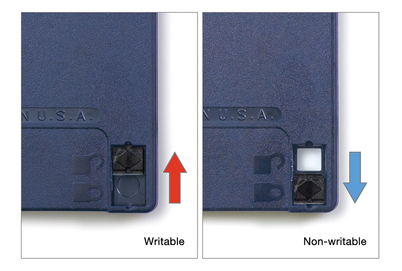
Make sure the disk write protect tab on the bottom of the disk is switched open, so it is write protected.
Put the disk into the drive with the metal shutter entering the drive first and the side of the disk with the circle facing down. It will click into place when completely inserted. See this video for a demonstration.
If the floppy disk seems like it stored files during the process of creation, consider whether this context is important to capture. If so, proceed to the Physical imaging section. If not, proceed to the Logical transfers section.
If the floppy disk cannot be read by the external drive or there are many errors, try using the internal 3.5” floppy drive with the Kryoflux.
Internal 3.5” floppy drive
...
The internal floppy drive needs to be connected via the Kryoflux controller card to the processing computer. The controller card allows a legacy internal drive to work through a USB connection. If this is your first time using the internal drive or Kryoflux, please contact the digital archivist for an initial training.
...
Next, connect the floppy drive power cord to the 4 pin molex adapter and then plug the other end into the 4 pin molex power cord (do not plug it into power yet, you must wait until step 7).
Always place the KryoFlux board on a non-conductive surface while it is in use. You may choose to use an anti-static mat or wristband, but typically this won’t be necessary and there’s debate about whether or not these types of anti-static devices will be helpful in a scenario like this one.
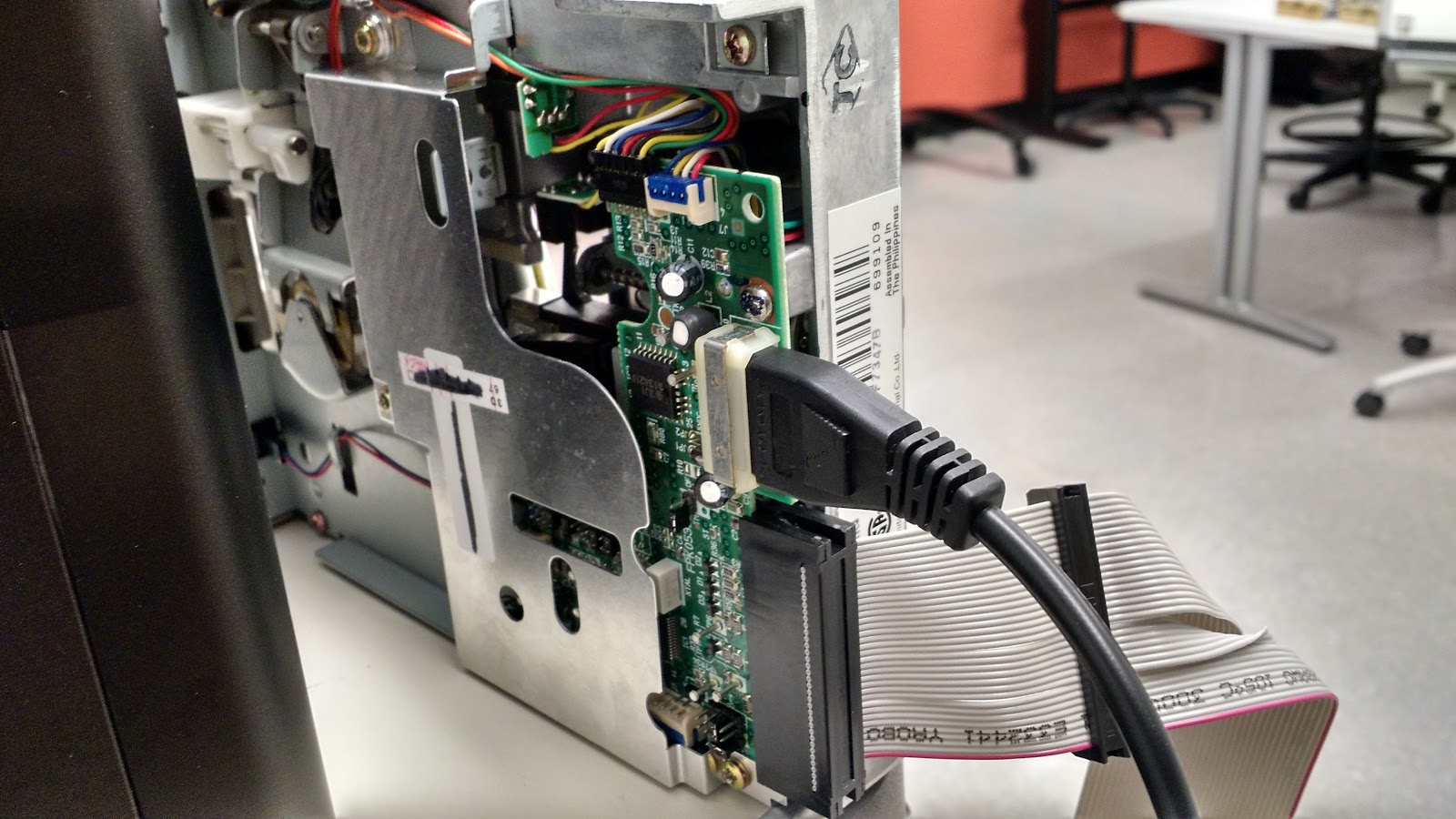
Enable write-blocking functionality by removing the jumper (small plastic cover) for the write gate (two pins below indicated in the image). It is most likely already removed and in the bag that the kryoflux is stored in. The board will look like the image below without any jumper in place.
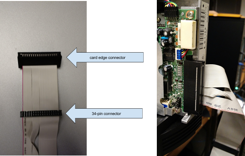
Connect the other end of the 34-pin floppy cord to Kryoflux. Make sure that the side with the red line is plugged into pin 1 (On the KryoFlux side, the cable’s first pin should be on the right if viewing the board with the cable connector closest to you. (As seen below)
Connect the KryoFlux board to the computer using the USB cable. The USB-A connecting end (white cord above) goes into the KryoFlux board and the standard USB connector goes into the processing computer.
Connect the power plug into power through a power strip. This step must be done last.
Take the floppy disk and slide the tab in the bottom corner so it is open. This enables write protection on the disk itself.
Put the disk into the drive with the metal shutter entering the drive first and the side of the disk with the circle facing down. It will click into place when completely inserted. See this video for a demonstration.
Proceed to the Kryoflux software section under imaging.


5.25” floppy drive
There are no standard 5.25” floppy drives that can be connected directly to computers currently in general use. You will need to use an internal floppy drive which needs to be connected via the Kryoflux controller card to the processing computer. The controller card allows a legacy internal drive to work through a USB connection. If this is your first time using the internal drive or Kryoflux, please contact the digital archivist for an initial training.
Place the drive on its side or with the circular part facing up or on the side of the drive. This is where the drive spins and should not be placed face down unless there is clearance underneath the spinning section.
Plug the edge connector into the drive with the pink line on left if looking a the drive horizontally from the back.
Plug the 4 pin molex power cord into the back of the floppy drive do not plug it into power yet, you must wait until step 7).
...
Get out the KryoFlux board. Always place the KryoFlux board on a non-conductive surface while it is in use. You may choose to use an anti-static mat or wristband, but typically this won’t be necessary and there’s debate about whether or not these types of anti-static devices will be helpful in a scenario like this one.
Enable write-blocking functionality by removing the jumper (small plastic cover) for the write gate (two pins below indicated in the image). It is most likely already removed and in the bag that the kryoflux is stored in. The board should look like the image below without any jumper in place.
...
Proceed to the imaging using Kryoflux software section. [link to Kryoflux software documentation section]
8” floppy drive
We have an internal 8” floppy disk drive but have not set it up for use. Contact the digital archivist if you encounter any 8” disks believed to be of high value.
Zip disk drives
...
We have an external Iomega 750 zip drive which can read Zip 100, 250, and 750 disks.
Connect the drive’s USB connector to the writeblocker and then connect the writeblocker to the processing computer. (see below under Hard drives and storage devices for instructions) If the drive is not recognized, attempt to connect it without the writeblocker.
Plug the DC cable into the back of the drive and the two prong plug into a standard wall outlet.
Insert the Zip disk with the metal shutter entering the drive first and the side of the disk with the circle facing down.
Proceed to the Imaging section for how to transfer the actual files.
Jaz disk drives
We have a SCSI connected Iomega Jaz drive but have not set it up for use. Contact the digital archivist if you encounter any Jaz disks believed to be of high value.
Optical disc drive
...
Our processing computers have an optical disk drive for CDs and DVDs. If you are using a different computer without an optical disc drive, use the USB connected disc drive.
If using the USB connected disc drive, plug it into your computer (the remaining steps are the same for either drive).
Press the small rectangular button on the front of the drive and it should pop open.
Place the disk label-side up on the tray, matching it up with the circular part of the tray.
Close the tray until you hear it click shut.
Proceed to the Imaging section for how to transfer the actual files.
...
Memory card reader
...
We have a multi-card reader that has a number of slots for memory cards.
Plug the USB connector into the write blocker and the write blocker into the processing computer’s USB port. See below for instructions.
Identify the type of memory card and insert it into the correct slot.
Proceed to the imaging or transferring materials section for how to transfer the actual files.
...